I have posted my crap over here as well because this is 1 more forum that I recognise as a place where people want to learn. Somewhere where the attitude isn’t just leech to get the hack working but find out how to make your own hack and why the hack works. As I always say
 Hack to learn, don’t learn to hack.
The Computer’s Number System
You may or may not know that a computer stores data as 0s and 1s. At a hardware level, a 0 is represented by a low voltage and a 1 represented by a higher voltage. Now then, in our normal system, we can have numbers ranging from 0-9. A computer only understands 0-1.
In a binary number system, we will have many of these 0s or 1s. Each one of these numbers is known as a bit. 8 of these bits put together is called a byte.
The number system that you use in everyday life is called the decimal system. Some of you may notice that decimal means that there are 10 (dec in latin is 10) possible combinations for each digit. This is clear since we can have 0, 1, 2, 3, 4, 5, 6, 7, 8, 9. In the binary system we are only allowed 2 combinations for each digit, 0 and 1.
Now then imagine when you’re counting up in 10, you go from 0 to 9 until 10. After 9, you know that there is nothing next so you put 1 onto the column next to it and reset the column that contained the 9.
In binary, it is exactly the same. You start with a 0, go to a 1. You can now see that we can no longer represent further combinations with 1 bit so the next value would be 10.
Now how do we convert binary to decimal ?
Okay, first of all, let’s look again at a decimal number: 842.
What does 842 mean ? Well it’s possible for us to look at it like this. We can say the first column (hundreds) represents how many lots of 100 there are. Now we can also write 100 as 10^2 (10 squared). The next column along (tens) represents how many lots of 10 we have. That column can be re-written as 10^1 (10 to the power of one). The last column represents how many lots of 1 we have. This can be re-written as 10^0 (10 to the power of zero), remember that anything to the power of 0 is 1. Therefore the value of 842 is:
8*(10^2)+4*(10^1)+2*(10^0)
The binary system is exactly the same except our base is not 10, but rather 2. Let’s look at the number : 10011110.
The number right on the left represents 2^7, the next one represents 2^6, and so on. Therefore we can say the value of 10011110 is:
1*(2^7)+0*(2^6)+0*(2^5)+1*(2^4)+1*(2^3)+1*(2^2)+1* (2^1)+0*(2^0) = 158 in decimal
A bit is pretty small though, I mean we can only hold 2 possible combinations inside a bit. Even in a byte (8 bits), we can only hold 255 different combinations (2^7+2^6+2^5+2^4+2^3+2^2+2^1+2^0, notice this is also equal to 2^8 – 1). Here are some larger sizes of data you might see:
Word - A word is 16 bits, or 2 bytes. Therefore we have 2^16 – 1 different combinations, that is 65535.
Double word – A double word (also known as a dword) is 32 bits, 2 words or 4 bytes. Therefore we have 2^32 – 1 different possible combinations, that is 4294967295.
Kilobyte - A measurement you might be a little more familiar with. A kilobyte represents 1024 bytes.
Megabyte - A megabyte represents 1024 kilobytes and therefore 1024*1024 bytes, that is 1048578 bytes.
Let me now introduce you to the hexadecimal system.
Hex = 6
Dec = 10
Hexadecimal = base 16. We have seen base 10 numbers and base 2 numbers now so base 16 shouldn’t be too hard to comprehend

In the hexadecimal number system, we have 16 different combinations for 1 digit: 0, 1, 2, 3, 4, 5, 6, 7, 8, 9, A, B, C, D, E, F.
0 = 0
1 = 1
2 = 2
3 = 3
4 = 4
5 = 5
6 = 6
7 = 7
8 = 8
9 = 9
A = 10
B = 11
C = 12
D = 13
E = 14
F = 15
This is just like before except we have a base 16 number so let’s say we are given the value : 2C8A, we can convert it into our decimal system by looking at it like this:
2*(16^3)+12*(16^2)+8*(16^1)+10*(16^0) = 11402.
Summary of Neccessities of Knowledge on the Intel 80×86 CPU Family
Registers
This section will consist of a gross oversimplification of the 80×86 CPU family and information on 32 bit 80×86 processor registers.
Before I get into describing assembly language instructions, I will explain to you a little about the CPU, memory and a little about I/O (input/output) devices. These three components are connected by the system bus. Out of these, I will go into more detail on CPU registers and the memory stack.
Within your CPU there are a number of processor registers. These small amounts of storage can be accessed faster than storage anywhere else. Almost all calculations on the 80×86 CPU involve a register. Registers will generally act as a middleman in a calculation.
You may have heard talk of 32 bit and 64 bit processors. Possibly you never understood exactly what that meant but one of the main differences is the range of addresses the processor is able to address to. A 32 bit processor can address to 2^32 different addresses. In hexadecimal, this is 00000000-FFFFFFFF. On the other hand, a 64 bit processor can address to 2^64 different addresses. In hexadecimal, this is 0000000000000000-FFFFFFFFFFFFFFFF. Yep, that’s 16 Fs instead of 8. Notice it is not double the amount as is so commonly thought but actually a 64 bit processor could actually address to the polynomial order 2 as many addresses as the 32 bit processor (ie. if you take the different number of combinations available for a 32 bit processor as x, the 64 bit processor can address to x^2).
Adding to this (since it isn’t strictly 100% correct), the “size” of your processor is either the minimum number of data lines on your CPU or the largest general purpose integer register. For example, all modern x86 processors have 64 bit buses (they can move 64 bits of data in one memory operation) but their largest general purpose integer register is only 32 bits. Therefore this type of processor would be classified as 32 bit.
(I was previously a little mixed up between the address bus and the data bus
 ).
).You will often see hexadecimal numbers in this form:
- Prefixed by 0x
eg. 0x2C8A
- Written with an ‘h’ on the end
eg. 2C8Ah
Decimal numbers may be seen in this form:
- Written with a ‘d’ on the end
eg. 11402d
Binary numbers may be seen in this form:
- Written with a ‘b’ on the end
eg. 10110010001010b
That was merely some background information to let you know what I mean by a 32 bit processor. Actually I want to show you what the registers are, how they are used and how you will use them in reverse engineering.
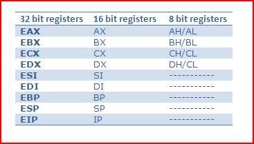
These are the names of 9 32 bit registers that you will become most familiar with:
EAX: Extended Accumulator Register
EBX: Extended Base Register
ECX: Extended Counter Register
EDX: Extended Data Register
ESI: Extended Source Index
EDI: Extended Destination Index
EBP: Extended Base Pointer
ESP: Extended Stack Pointer
EIP: Extended Instruction Pointer
Although each register has a purpose, a lot of the time you can use them for whatever you like. However you must always follow this rule. If you are to use a register, you must make sure that after you finish using it, it ends up with the value it was holding before you used it.
One particular register from the above I would like to point out is EIP. This register holds the address to the next instruction the processor will execute. In fact in one of the parts of my reversing series, I will demonstrate how this register’s value can be manipulated to control the flow of the code execution.
The 32 bit registers described above can hold 32 bits of data (4 bytes/a dword).
EBP and ESP are related to the memory stack which I will be explaining a little about later but it’s nothing you have to worry about yet.
Now, as well as having 32 bit registers, we have 16 and 8 bit registers too.
Note that the 16 and 8 bit registers are NOT separate from the 32 bit registers.
I don’t know how I can emphasise this more but it is essential that you understand this. The registers are not separate. The 80×86 overlayers 32 bit registers with 16 bit registers with 8 bit registers.
The lower parts of EAX, EBX, ECX and EDX are called AX, BX, CX and DX respectively. AX, BX, CX and DX are 16 bit registers meaning they can hold 16 bits of data (2 bytes/a word). Now these four 16 bit registers are also split into higher and lower parts. The higher parts are called AH, BH, CH and DH. The lower parts, AL, BL, CL and DL. The four 32 bit registers described above are called general purpose registers.
Each of the other 32 bit registers also have 16 bit registers within them but there are only the four 8 bit registers mentioned above. This table summarises what I have been talking about:

To better consolidate your memory I will give an example of how the registers interact with each other.
Let us take for example the value of EAX to be:
7FEDCBA0
Now AX is the lower word or 16 bits of EAX. Therefore the value AX holds is:
CBA0
AH holds the higher part of AX and therefore holds:
CB
AL holds the lower part of AX and therefore holds:
A0
All good ? Understanding of this is critical to reverse engineering otherwise you’ll never know how certain values got to be where they are.
Flags
However I have missed out one very special register till the end. This is the EFLAGS register. It is a 32 bit register holding single-bit boolean values. Boolean means the state of the value is either true or false. Did you ever wonder what happens when a processor is executing instructions ? Most of the time, code execution does not just go down vertically but jumps around. How do we control where we jump to ? Well we use conditional jumps. This is the equivalent of a higher levelled syntax such as IF. It eventually results down to a bunch of conditional jumps.
8 of the bits inside the EFLAGS register are of particular interest to you when reverse engineering. These bits are called flags. Flags can hold two states, 1 or 0. A flag in the state 1 is said to be set and a flag with a state of 0 is said to be clear. The conditional jumping of code I mentioned above depends on the status of one or more flags. In fact I have only seen one conditional jump so far that does not depend on the status of a flag/s (JECXZ – jumps when ECX = 0) so hopefully you will realise how important flags are. Because flags basically control a program’s flow of code execution this is another way we are able to manipulate exactly what happens when we run an application. I will describe 3 of the more important flags:
Z-Flag – The zero flag is set or cleared depending upon the result of the prior instruction. If the result of the prior instruction was 0, then the Z-flag is set (1), otherwise the flag stays clear (0).
O-Flag – The overflow flag is set when the prior instruction resulted in the register operated on to undergo a change in its highest bit.
C-Flag - The carry flag is set if you add a register’s value exceeds FFFFFFFF or is less than 0.
And that’s all you will need to know about registers and flags to being reversing.
The Memory Stack
The memory stack is a part in your computers memory you can use to temporarily store data. This data could be an address, a constant, etc. Think of the stack as a massive box that is available for you to stack pieces of paper. When you put something onto the stack, it is called a push. When you remove something from the stack, it is called a pop. Now let’s pretend you really had a stack and you wanted to put things onto this stack. Well if I had just piled up 10 pieces of paper on top of each other in my stack and I wanted to remove the one at the bottom, I can’t just pull it out. Instead I would have to remove every other piece on top of it first before being able to get at the piece at the bottom. This is the most important rule about stacks. The first thing to be pushed onto the stack is the last to come off. In practice, there are a few exceptions to this but I won’t go into detail. This also goes for the other way round too. Whatever you last put onto the stack is the next thing you take off unless you put something else on.
Assembly Instructions
What is the assembly language ? As a reverser you will be seeing the most of assembly language. In general, you will be examining the disassembly of an application. This means looking at direct instructions that the processor is following. At the end of the day all computer languages are translated down to assembler.
Most instructions in the assembly language have an operation code followed by two operands. However there can be more or less operands depending on the operation code used. Operation code is also known as opcode. These are similar to the syntaxes you may use in other programming languages except that these are direct instructions to your processor. These instructions are also known as mnemonics. Bear in mind that mnemonics are just easier words that you can remember. They are actually translated from bytes that a processor reads. All values in the assembly language’s mnemonics are always hexadecimal.
A typical instruction would be in the form:
OPCODE DESTINATION,SOURCE
Now then I briefly mentioned before about jumping. There are two
types of jumps, conditional jumps and non-conditional jumps.
Non-conditional jumps will lead to a jump no matter what. A jump will
let you skip code and take code execution elsewhere. The opcode for a
non-conditional jump is JMP. For example, if I wanted to jump to
00400000, this would be the instruction:JMP 00400000
There are many, many conditional jumps so I have bolded the ones that you will meet most frequently (this is not a full list):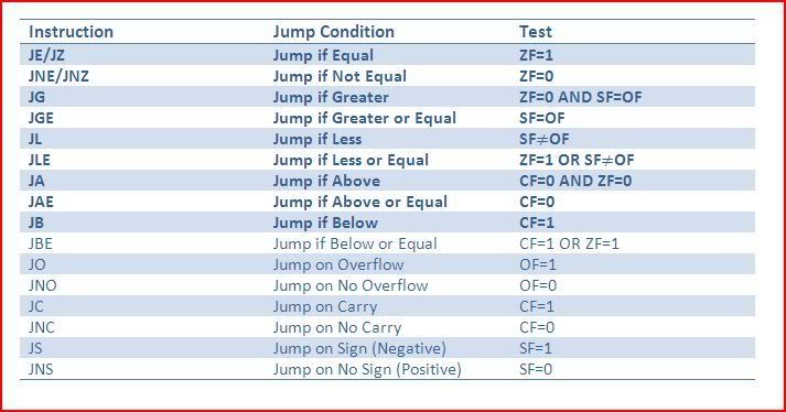
And that’s all for conditional jumps. I will now go through the other assembly instructions that you are most likely to come across:
MOV – This is the move instruction. It will take two operands and operate on them. You may think of it as copying instead of moving since the operand copied from does not lose its value. The operands that are available are registers, addresses or values.
MOV DESTINATION,SOURCE
The following instructions would be available:
MOV X,Y; Moves Y to X
MOV X,[Y]; Moves what is stored in Y to X
MOV [X,]Y; Moves the value of Y into X’s value
When there are square brackets such as [X], then it means the contents of X.
CMP - Compares the two operands and sets C/O/Z flag accordingly.
CMP DESTINATION,SOURCE
For example, this instuction:
CMP EAX,[400000]; Compares EAX with the value held at 400000
INC - Increments the value.
For example, this instruction:
INC EAX; Increases the value of EAX by 1
DEC - Decrements the value.
For example, this instruction:
DEC EAX; Decreases the value of EAX by 1
ADD - Adds two operands. The result is stored in the destination address/register.
ADD DESTINATION,SOURCE
For example, this instruction:
ADD EAX,5; Adds 5 to the value of EAX and stores result in EAX
SUB - Subtracts the source from the destination and stores the result in the destination address/register.
SUB DESTINATION,SOURCE
For example, this instruction:
SUB EAX,5; Subtracts 5 from EAX and stores result in EAX
[b]CALL – Pushes a RVA (Relative Virtual Address) of an instruction onto the memory stack and calls a sub program/procedure/function.
You can call with the following methods:
CALL 40000 ; Call an address
CALL EAX ; Call 3register
CALL DWORD PTR[EAX] ; Call the address stored at EAX
CALL DWORD PTR[EAX+5] ; Calls address stored at [EAX+5], notice you can do small calculations
DIV – DIV divides EAX by a divisor. The dividend is EAX as is the where the result is stored. The modulo-value is stored in EDX, ie. the remainder.
For example, these instructions:
MOV EAX,9
MOV ECX,2
DIV ECX
EAX would end up holding 4 and EDX, 1 because 9-(4*2).
IDIV – The same as DIV except it can handle signed numbers. A signed number means it can be positive or negative. The I is an abbreviation for integer (division).
MUL – Multiplies either EAX with a value or multiplies two values and puts them into a destination register or it multiplies a register with a value.
For example, these instructions are available:
MUL VALUE
MUL DESTINATION,VALUE,VALUE
MUL DESTINATION,VALUE
IMUL - Integer multiplication, the same as MUL except you can use signed numbers.
INT - Calls an interrupt handler. The value called must be an integer.
For example, this instruction:
INT 21
LEA - Load effective address. Usually used for doing calculations for addresses quickly.
For example, this instruction:
LEA EAX,DWORD PTR[2*EBX-ECX]
Would give EAX the value of 2*EBX-ECX.
NOP - No operation. Does nothing, literally
We often use this to overwrite calls, etc. so that instead of that call or instruction, nothing will happen.RET - Returns after a CALL instruction. The return digit cleans the stack before returning.
For example, this instruction:
RET 4
TEST – Performs the logical AND instruction on two operands and results are used to set or clear Z-flag (more on bitwise operators later). Overflow and carry flags are also cleared with this instruction.
For example, this instruction:
TEST EAX,EAX
The last two instructions of interest are PUSH and POP but we’ve already covered those to a certain extent. Just remember with the stack the first in, last out rule.
I mentioned signed numbers with IDIV and IMUL. You may be wondering how a binary system can represent negative and positive numbers. One way is to use one of the bits to state whether the number will be positive or negative. Therefore although the range of numbers stays the same, the numbers available are not. For example, in a 8 bit register, there can be 256 different combinations. However the range of the numbers is actually -128-0 and 0-127.
Logical Bitwise Operations
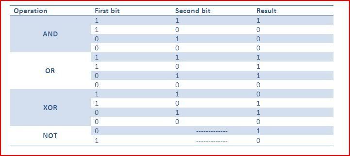
A bitwise operation is used to operate on one or two bit patterns (set of binary numbers). I will be covering the following bitwise operations:
- AND
- OR
- XOR
- NOT
The AND operation will result in a 1 only if both corresponding bits are one (ie. the first one and the second one). Everything else will result in a 0.
The OR operation will result in a 1 if either bit has a one (ie. the first one or the second one). Therefore only if the two bits to be operated are zero will the result be a zero.
The XOR operation will result in a 1 only if one of the bits has a one. XOR means exclusive OR which means either one but not both.
The NOT operation will result in a 1 if the bit is a 0 and will become a 0 if it is a 1.
This table shows all possible combinations for the four bitwise operators described above:
Now then to demonstrate about a bitwise operation, I will explain a little about the ASCII table. ASCII (American Standard Code for Information Interchange) is an encoding system based on the english alphabet. ASCII codes are used to represent every character you will write. Remember what I said earlier about how assembly instructions always deal with hexadecimal values ? Well if I was given the following instruction:
XOR 1SLUG,SNACK
First of all, I would have use an ASCII table to convert each character into a hexadecimal value.
An ASCII table can be found at:
http://www.asciitable.com/
1SLUG –> 31,53,4C,55,47
SNACK –> 53,4E,41,43,4B
Now we need to convert to binary to do the XOR operation:
31,53,4C,55,47 –> 0011 0001 0101 0011 0100 1100 0101 0101 0100 0111
53,4E,41,43,4B –> 0101 0011 0100 1110 0100 0001 0100 0011 0100 1011
It’s good that they’re lined on top of each other because now it’s easy to see where there are 0,1 or 1,0. The result should be:
0110 0010 0001 1101 0000 1101 0001 0110 0000 1100
Converting back to hexadecimal gives:
62,1D,0D,16,0C
Converting from that to normal characters gives:
b[GS][CR][SYN][FF]
Notice that the last four characters aren’t normal writable ones. I used a bad example in this case but you get the idea hopefully. In practice, we wouldn’t go doing this by hand. There are many programs to do this or in fact Windows calculator contains a hex<–>dec<–>bin converter that you may use as well as several common bitwise operations.
As always if there is anything you do not understand, feel free to ask and I’ll explain to the best of my ability.
OllyDbg
One of the most popular debuggers for reverse engineering. OllyDbg is a Ring3 debugger, if you don’t know what that means, that’s not a problem at all. To “install” it, simple go to http://ollydbg.de/, download Olly and extract it to a folder and you’re ready to go ! You may also find helpful the Win32 help files for help with APIs:
http://allserv.ugent.be/~fschoonj/modula2/win32hlp/win32.zip
Just download and extract to a folder and show Olly the path in Help >> Select API Help File and select win32.hlp.
I won’t explain too much here since I think it’s best to learn about it as you actually use it but I’ll label the windows in an image:
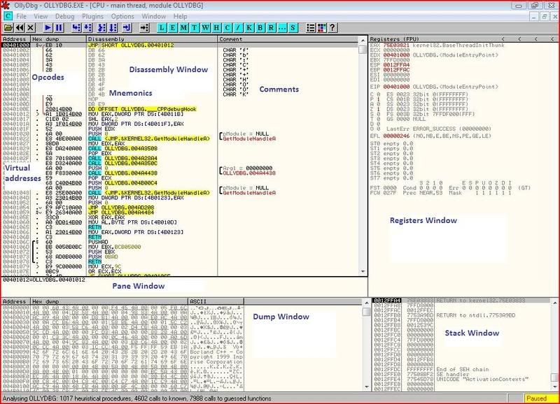
That’s all, you should be able to start playing around with Olly and understand vaguely what is happening. As always if you have any questions at all, don’t hesitate to ask.
No comments:
Post a Comment